By: Giusy Gambino, Sebastiano Grasso, and Filippo Scrimizzi STMicroelectronics
Integrated smart power devices are becoming increasingly crucial in automotive systems due to their ability to combine power management with advanced diagnostic and protection features. When a fault occurs, these features enable the connected control unit to react promptly and effectively, protecting both the vehicle and its occupants. Smart power devices are often responsible for critical tasks within a vehicle and are gradually replacing conventional components such as fuses and relays, and switches.
Electronic fuses, a prominent type of smart power device, are particularly remarkable for their reliability under harsh environmental conditions, including high operating temperatures and mechanical stress. Additionally, they have to withstand various forms of electromagnetic interference (EMI) that can affect their normal functionality. This is especially crucial in safety-critical applications like airbag control modules or Anti-lock Braking Systems (ABS), where precise operation is vital to avoid hazardous conditions and ensure functional safety.
Testing Procedure for EMI
To ensure the correct operation of electronic products, they need to be tested for electromagnetic emissions that may negatively affect nearby equipment. These emissions fall into two categories:
- Conducted noise, which travels through supply or data/control cables.
- Radiated noise, which propagates through free space.
CISPR 25 is the standard developed for vehicles and boats to protect on-board receivers from such emissions. It outlines both limits and methods of measurement for equipment on board.
Conducted emission limits typically cover a frequency range of 150 kHz to 200 MHz, although this range may extend down to 9 kHz. The limits are defined in terms of average, quasi-peak and peak values.
Peak detection retains the peak value of each harmonic in an emitted signal, indicating the worst-case scenario. Average detection provides the average amplitude of each signal component across its period. Quasi-peak detection weighs each component based on its repetition rate: the faster the repetition rate, the higher the weight given to that component.
The output response of the three detectors to two similar pulsed signals is shown in with the top one having a higher repetition rate.
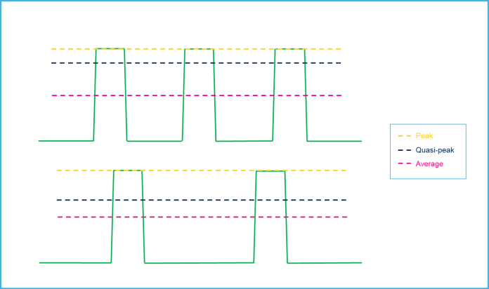
The above picture shows that the quasi-peak detector has a higher voltage output when the event occurs more frequently.
To determine the conformance of the Equipment Under Test (EUT) with the specified CISPR 25 limits, the following guidelines should be followed (Fig. 2).
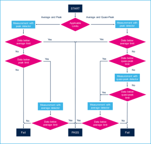
In all cases, the EUT should conform to the average limit. For frequencies where both peak and quasi-peak limits are defined, the EUT should conform to either the peak or the quasi-peak limits, as specified in the test plan. For frequencies where only peak limits are defined, the EUT must conform to the peak limit.
For CISPR 25, emission limits are divided into Class 1, 2, 3, 4, and 5 products, specifying how to measure the noise using peak, quasi-peak, and average detection methods (Tabs. 1 and 2).
| Service/Band | Frequency MHz | Levels in dB (µV) | ||||
| Class 1 | Class 2 | Class 3 | Class 4 | Class 5 | ||
| Peak | Peak | Peak | Peak | Peak | ||
| BROADCAST | ||||||
| LW | 0.15 – 0.30 | 110 | 100 | 90 | 80 | 70 |
| MW | 0.53 – 1.8 | 86 | 78 | 70 | 62 | 54 |
| SW | 5.9 – 6.2 | 77 | 71 | 65 | 59 | 53 |
| FM | 76 – 108 | 62 | 56 | 50 | 44 | 38 |
| TV Band I | 41 – 88 | 58 | 52 | 46 | 40 | 34 |
| MOBILE SERVICES | ||||||
| CB | 26 – 28 | 68 | 62 | 56 | 50 | 44 |
| VHF | 30 – 54 | 68 | 62 | 56 | 50 | 44 |
| VHF | 68 – 87 | 62 | 56 | 50 | 44 | 38 |
Tab. 1 Emission limits for the different classes with peak noise detection.
| Service/Band | Frequency MHz | Levels in dB (µV) | ||||
| Class 1 | Class 2 | Class 3 | Class 4 | Class 5 | ||
| Average | Average | Average | Average | Average | ||
| BROADCAST | ||||||
| LW | 0.15 – 0.30 | 90 | 80 | 70 | 60 | 50 |
| MW | 0.53 – 1.8 | 66 | 58 | 50 | 42 | 34 |
| SW | 5.9 – 6.2 | 57 | 51 | 45 | 39 | 33 |
| FM | 76 – 108 | 42 | 36 | 30 | 24 | 18 |
| TV Band I | 41 – 88 | 48 | 42 | 36 | 30 | 24 |
| MOBILE SERVICES | ||||||
| CB | 26 – 28 | 48 | 42 | 36 | 30 | 24 |
| VHF | 30 – 54 | 48 | 42 | 36 | 30 | 24 |
| VHF | 68 – 87 | 42 | 36 | 30 | 24 | 18 |
Tab. 2 Emission limits for the different classes with average noise detection.
LW stands for Long Waves
MW for Medium Waves
SW for Short Waves
TV Band I for TeleVision broadcast Band 1
CB for Citizens Band
VHF for Very High Frequencies.
The testing procedure ensures that both peak and average measurements are checked for compliance with Class 5 standards. If any measurements fail, the EUT is evaluated against a lower class.
Conducted Electromagnetic Emission
The conducted Electro-Magnetic Emission (EME) is the noise current generated by the EUT that propagates through the harness to other components/systems or power grid. This noise current can be measured using either the voltage method or the current method.
The voltage method is carried out with the measurement setup displayed in Fig. 3.
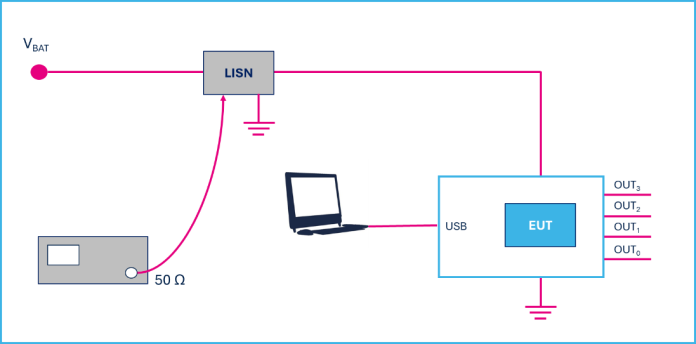
LISN stands for Line Impedance Stabilization Network.
Experimental Results
The experimental data have been collected for the STi2Fuse product VNF9Q20F, which is a 4-channel monolithic electronic fuse fully programmable through serial peripheral interface (SPI). This device embeds sophisticated digital protection and diagnostic mechanisms, which include a unique i2t feature for harness protection.
The following testing conditions have been considered:
- VBAT = 13 V
- TAMB = Room temperature
- All channel in Fail Safe mode (off)
- Channel 2 driven by direct input with DC (5 V) and PWM (100 Hz, 50% duty cycle) loaded with 27 W + 5 W bulbs.
When channel 2 is turned on and it is driven by direct input with 5 V DC voltage and a PWM signal with 100 Hz frequency and 50% duty cycle, the noise detector measurements for peak and average methods are shown in Fig. 5 and compared with CISPR 25 limit relevant to class 5.
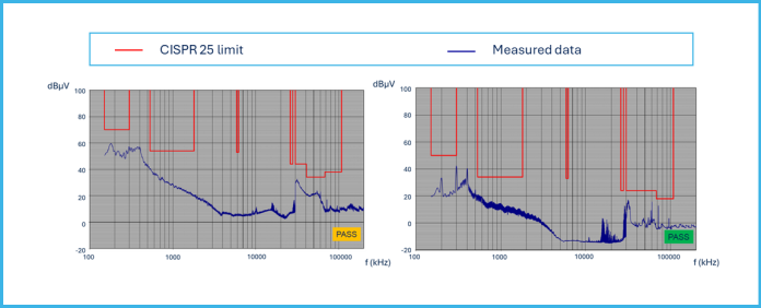
The electronic fuse VNF9Q20F is able to pass all the limits imposed by CISPR 25 for both peak and average limits in class 5.
Conclusions
The EMI behavior of a smart electronic STi2Fuse device has been investigated, demonstrating compliance with the CISPR 25 standard under class 5 specifications.
The STi2Fuse products are critical components in modern vehicles, providing overcurrent protection and ensuring the safe operation of electrical circuits. Compliance with the CISPR 25 standard, particularly under class 5 specifications, is essential for these devices to ensure they do not interfere with other components and equipment within the vehicle.
References
[1] VNF9Q20F, 4 channel high-side driver with STi2Fuse protection for automotive power distribution applications.
[2] CISPR 25:2021 International Standard, Vehicles, boats and internal combustion engines – Radio disturbance characteristics – Limits and methods of measurement for the protection of on-board receivers, Edition 5.0, Dec. 2021.
[3] R. Letor, R. Crisafulli, Smart Power devices and new electronic fuses compliant with new E/E architecture for autonomous driving, AEIT International Conference of Electrical and Electronic Technologies for Automotive (AEIT AUTOMOTIVE), 02-04 July 2019


