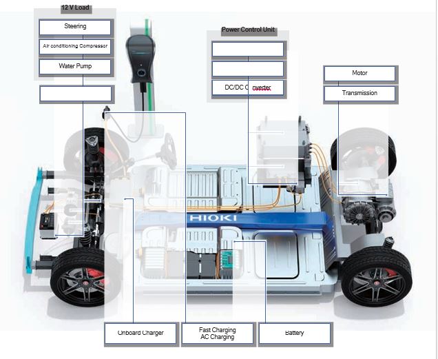
Hioki offers a diverse array of motor measurement solutions that can be used in applications ranging from performance analysis to quality testing. The ability to assess and analyze using high-precision measurement technologies provides valuable assistance to engineers as they work to increase motor performance and quality.
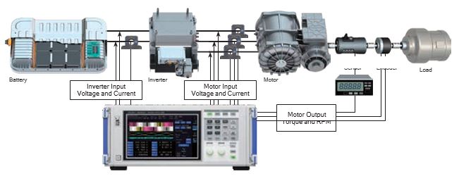
Evaluating Inverter Motor efficiency and Loss
Simultaneously measure inverter input and output power, and motor output. Evaluate inverter, motor, and overall system efficiency and loss in an accurate and highly reproducible manner.
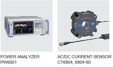
PW6001

- Power measurement (6 channels with 1 instrument or up to 12 channels by connecting 2 instruments)
- Basic accuracy (power) of ±0.05%
- Waveform analysis without an oscilloscope; triggers specifically designed for motor analysis
Inverter Motor ECU Measurement and Compliance Testing
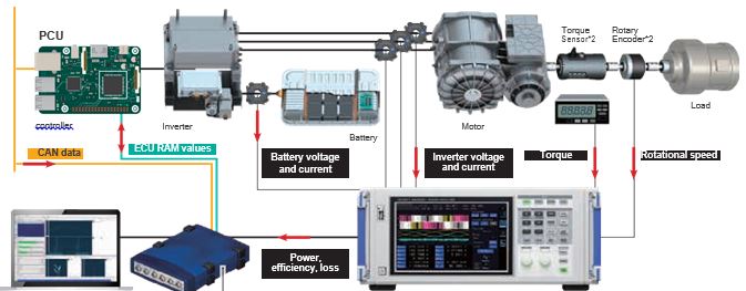
Make quick work of PCU compliance testing by taking advantage of PW6001 and INCA*1 link functionality so that you can use the PW6001 to perform accurate power and motive power measurement. You can simultaneously monitor CAN bus data and ECU RAM values.
Increase efficiency of measurement experiments and calibration INCA measurement, calibration, and diagnosis tool*1
• Parameters can be rewritten during PCU operation
• High-speed monitoring of ECU RAM
- Aggregate data from multiple measurement systems and buses into one intensive software
Measuring dynamic motor characteristics
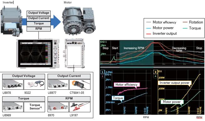
Record inverter output voltage and current, torque, and RPM from motor start to stop. Calculate inverter output power, motor power, and motor efficiency using waveform calculations.
Calculate inverter output power, motor power, and motor efficiency using waveform calculations
Calculate motor power, motor efficiency, and inverter output power after measurement using high-speed waveform calculations and display the results using the instrument’s X-Y display function. The ability to use the X-Y display for waveform calculation results as well as input signals from measurement units means you can perform a broad range of analyses. Additionally, X-Y analysis can be performed at user-specified areas of the recorded fluctuating waveform, since you can choose waveform areas for generating an X-Y display.

Measuring motor torque vibrations
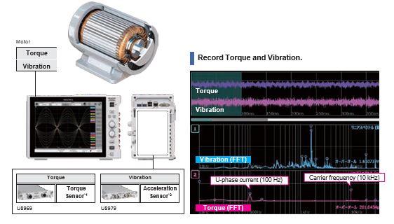
Measure torque and vibration, and analyze behaviour during motor operation. Discover resonance phenomena and other unpredicted frequency component by FFT calculations to perform frequency analysis.
Perform Frequency Analysis Using FFT Calculations
The MR6000/MR6000-01’s FFT calculation functionality can be used to perform frequency analysis of torque and vibration signals. The MR6000/MR6000-01’s FFT calculation functionality can analyze 8 phenomena simultaneous per measurement. By performing FFT analysis of signals input to different channels, it is possible to analyze frequency components occurring at the same time on different channels.

Measuring Resolver rotation angles
A resolver is used as a sensor to accurately measure the angular position of the motor. Resolvers are used in harsh environments such as industrial motors, servers, and electric vehicles (EVs) because they can operate under demanding conditions for an extended period of time.
Calculate The Resolver’s Rotational Angle Using Waveform Calculations

The resolver’s excitation signal and output signal are input to the 4ch Analog Unit U8978. Since setups that would have required two slots with previous models can be accommodated with a single slot, there’s capacity left over to measure temperature, control signals, torque, and current signals at the same time. The instrument’s waveform calculation function is used to calculate the resolver’s rotational angle. Motor control sequences can be adjusted by analyzing the relationship between the resolver rotation angle and other signals.
Courtesy: Hioki


